Inverted pendulum 2024
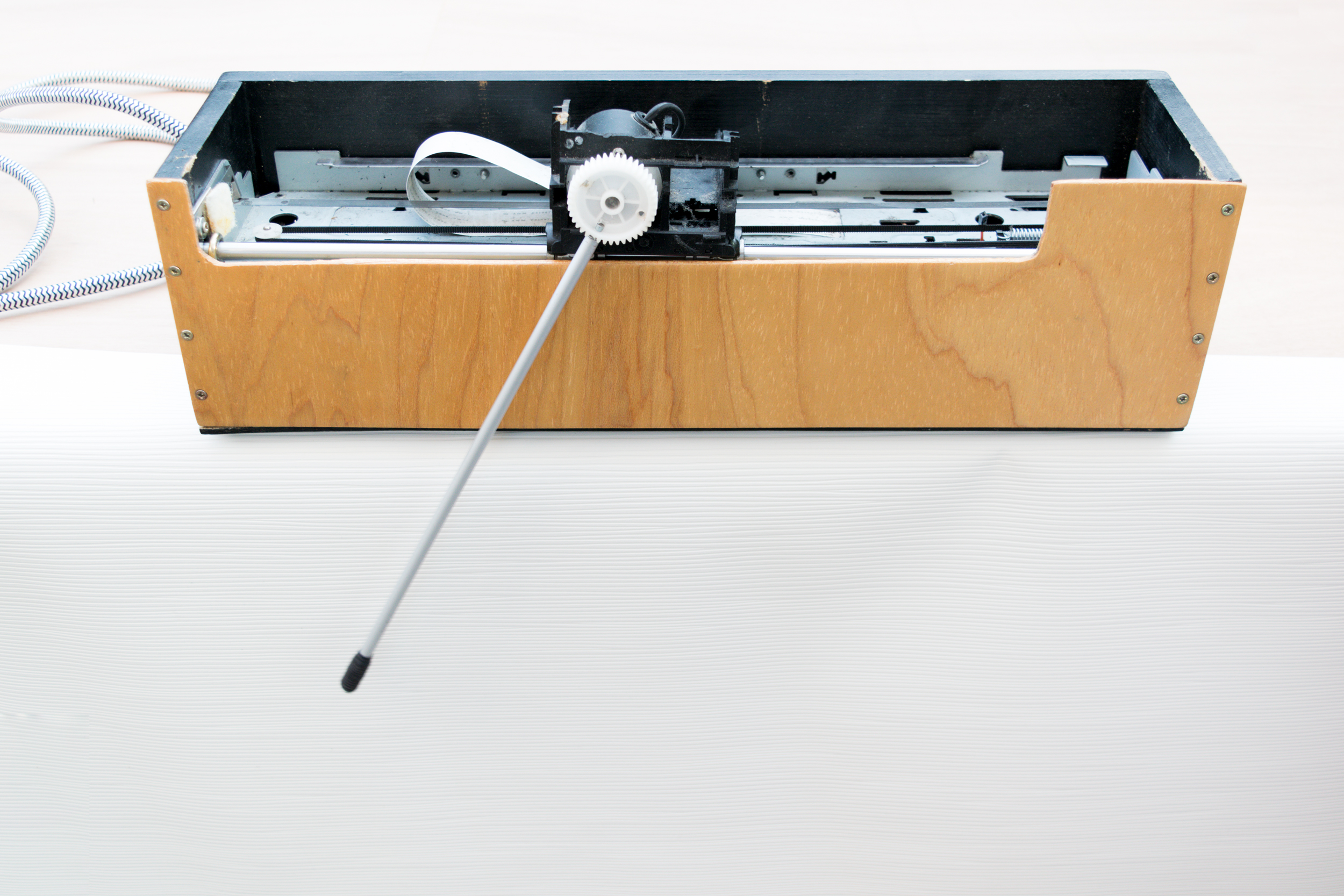
After 10 years of collecting dust, the inverted pendulum is ready for an update. In the meantime, there have been many developments in IoT, and my programming skills have also improved significantly. The main goal is to transform the pendulum into an independent art object requiring only a power plug. To achieve this, the pendulum needs to be wireless and controlled with a remote.
To accomplish this goal, I replaced the Arduino with an ESP32, adapted a Python interface script originally created for controlling LED strips to run on my iPhone, and developed another Python script for my laptop to visualize data from the controller. In the following sections, I will provide more detailed information about the different components of the new setup.
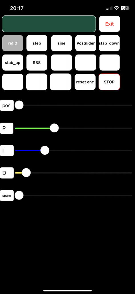
iPhone remote control
Functions:
- Choose mode of pendulum
- Home position
- Step response
- Track Sine
- Track User position input
- Stabilise in downward position
- Stabilise in upward position
- RBS
- Tune parameters of PID controller
Footage of the setup
The upward position controller is functional but still suboptimal. The next step involves integrating state feedback, ideally utilizing a model-based observer. This approach allows accurate estimation of both the cart’s velocity and the pendulum’s state without delays. Additionally, identifying the transfer function from motor voltage to acceleration will enable precise pendulum control.
Live controller tuning
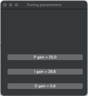
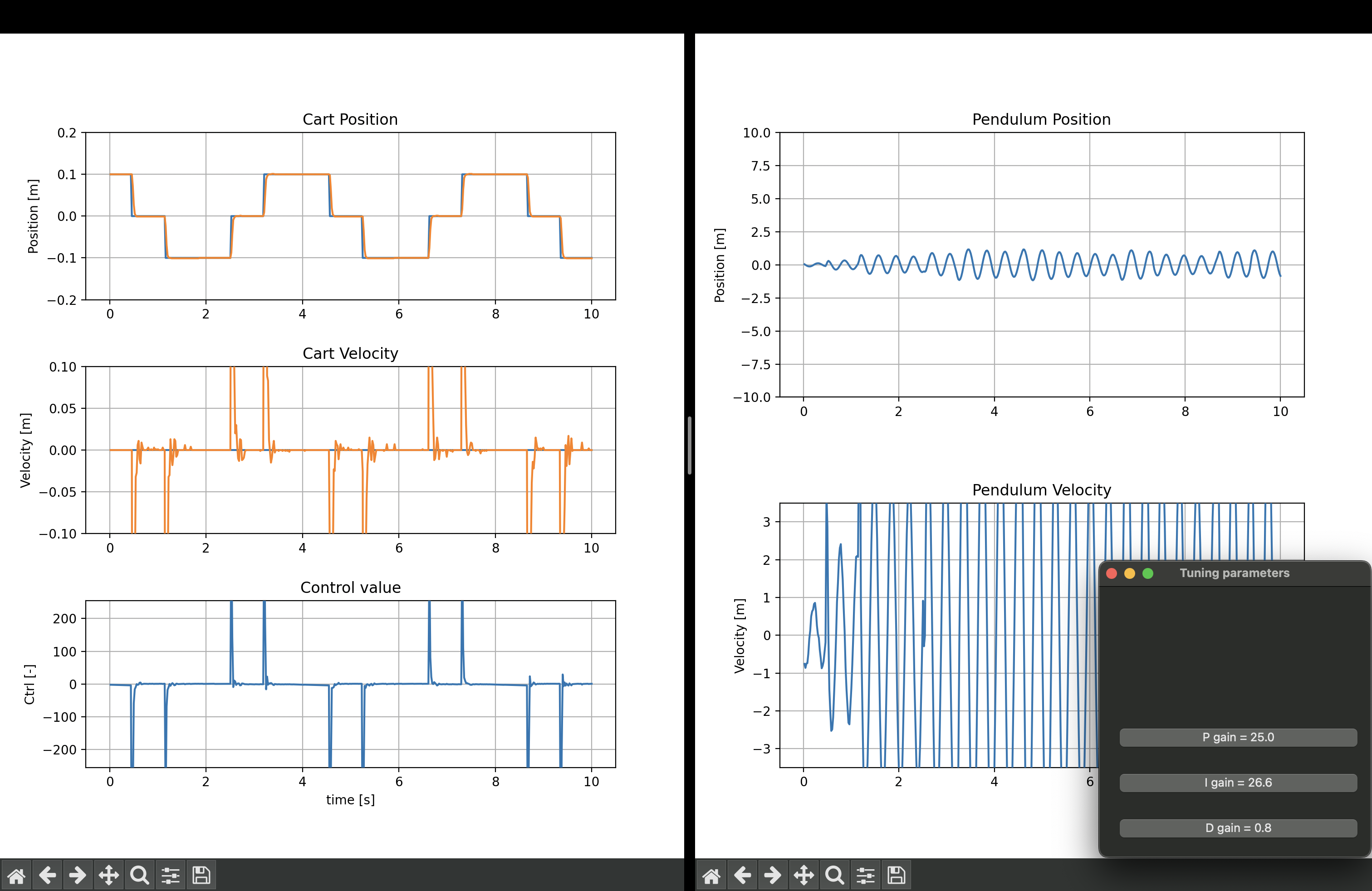
Three of the DMX sliders in the iPhone remote control app are designated for tuning the PID controller. The current values are displayed in a pop-up screen for easy monitoring.
This setup evokes a sense of how controller tuning was conducted in the pre-computer era. Back then, analog electronic circuits were used for feedback control, and parameters were adjusted using potentiometers. Tuning a live controller provides valuable insights into how each component contributes to the overall control signal.
Original inverted pendulum story
A classic device that challenges control engineers.
I built one myself just for fun, and it works perfectly, so check it out!
For those interested, here is some background information:
Hardware
The machine is based on an old HP inkjet printer, which is ideal for several reasons: Firstly, it offers a perfect opportunity to recycle an old domestic appliance, and secondly, it provides suitable hardware for the intended purpose. The cart position is measured using the original HP optical encoder, boasting 6800 lines over a span of 200 mm! The pendulum angle is measured with a rotary optical encoder featuring 600 lines per revolution.
The encoder increments are counted on an Arduino. Additionally, the original belt-driving DC motor that propels the cart is controlled by the Arduino through a motor driver. The actual controller—the heart of the pendulum—is MATLAB-based. The Arduino primarily serves as an interface between the hardware and the computer. Through serial communication, the voltage reference is sent, and the measured positions are received.
Software
There are two control modes: swing-up mode and stabilizing mode. In swing-up mode, an energy function guides the cart to continually add energy to the pendulum until it reaches a specific angle.
Once the swing-up angle is attained, stabilization occurs through state feedback. To estimate the states, a 5th-order discrete-time observer was derived via system identification using a random binary signal (RBS). It required several attempts to gather sufficient data while staying within the physical limits of the cart’s guiderail, but the resulting model proved highly accurate.
The state feedback controller was tuned using LQR (Linear-Quadratic Regulator). This method allows direct manipulation of states using control parameters, simplifying tuning significantly since I identified the controller in canonical form. Here, states represent pure time derivatives—positions, velocities, and accelerations. By incrementally tuning the controller, the pendulum is stabilized while the cart simultaneously tracks a reference.
